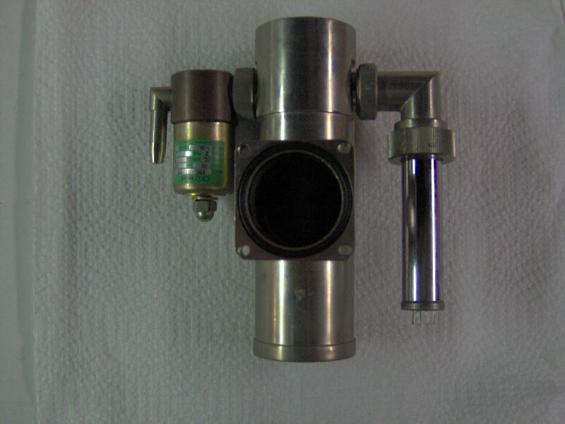
Scanning Electron Microscope - High Vacuum System
I didn't think to get a picture of the SEM's
high vacuum system in its original condition, but the problems were all
internal, so a picture wouldn't have been very helpful. This is a
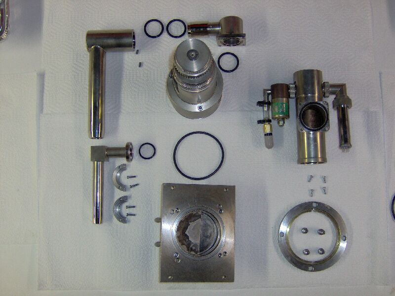
picture of the disassembled system, spread out on a work bench.
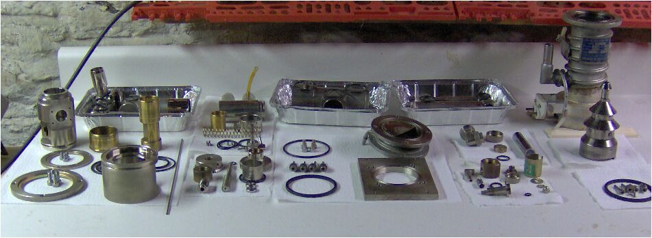
The pans in the back contain various pieces of the manifolds which
connect the system to the rough pump and to the column of the microscope.
Between the pans are the parts of the pilot actuated anti-suck-back valve.
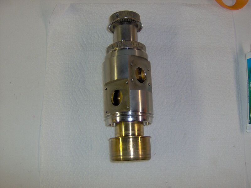
On the left are the parts of the main, three-way, high vacuum valve and
a piece of 3 mm hardened stainless steel shafting from which a new poppet
anti-rotation shaft will be made (the original was destroyed during the
previous disassembly attempt). Left of center are the parts of the
valve drive. Center is the mounting plate and water-cooled baffle.
On the right are a vacuum gauge and up-to-air solenoid valve. Far
right is the diffusion pump, with the jet assembly removed.
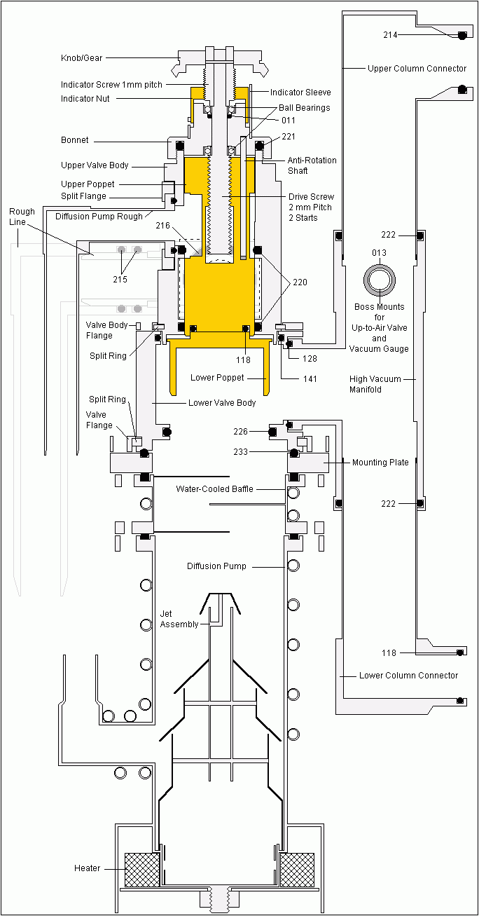
Here is a drawing (to scale) of how the parts go together, o-rings are
labeled with their aerospace standard AS568A size.
OK, just spent ~$300 on o-rings, tubing, tubing clamps, etc.
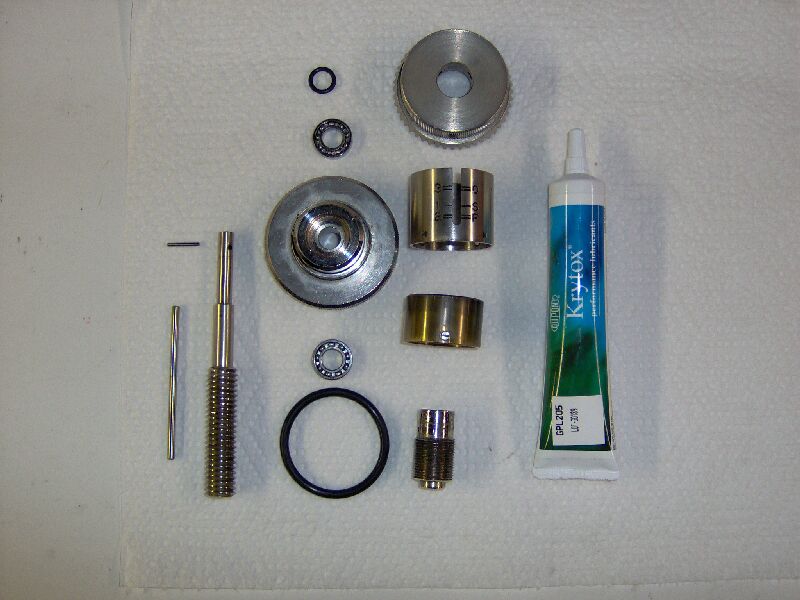
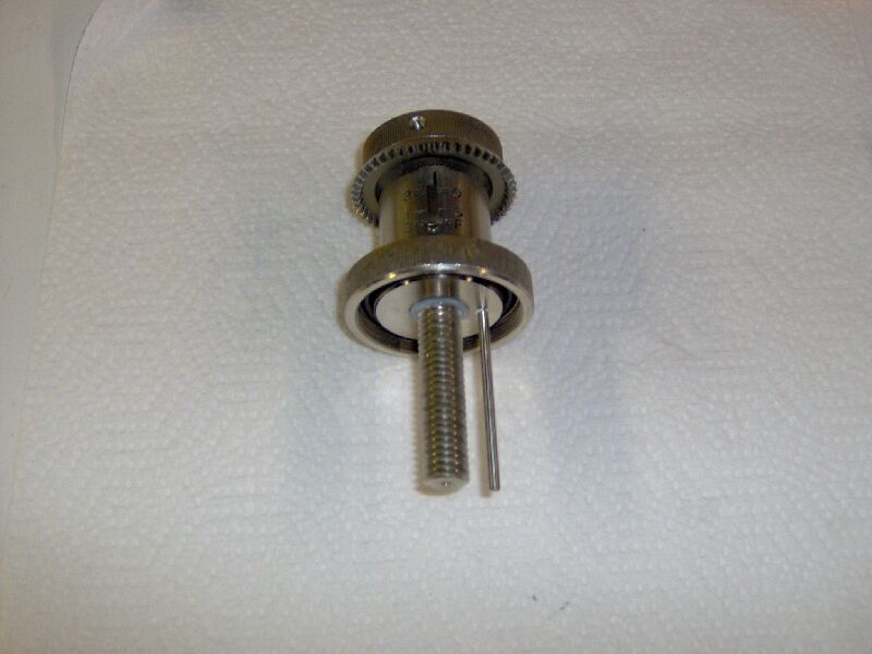
Let's put it back together. Here are the parts for the bonnet and
valve actuator assembly. The new anti-rotation shaft and a new lead
screw to indicator screw pin (the original snapped when I tried to remove
the jammed poppet by turning the handle) can be seen to the left of the
lead screw.
Pack bearings, coat threads and o-rings with Krytox(RTM) GPL grease
and assemble: bearing on lead screw shaft, shaft and bearing into bonnet,
o-ring and bearing over shaft, indicator screw over shaft and pin in place,
indicator nut screwed on, followed by indicator sleeve, gear/knob secured
to indicator screw with three set screws, anti-rotation shaft pressed into
bonnet (with a wee bit of teflon tape to hold it securely) and the bonnet
seal o-ring pressed into groove.
Next, o-rings lubed and installed in upper half of valve body, bonnet
screwed onto the upper half of the valve body, upper and lower poppets
joined with screws and o-ring, joined poppets slipped into upper body section
over the anti-rotation shaft and actuator lead screw threaded into the
upper poppet.
Final step (of valve assembly), lube and install o-rings in lower half
of valve body, slide upper half into lower, install split ring in groove
of upper half, slide flange over split rings, bolt flange to lower body
half, align indicator with poppet and screw indicator sleeve to bonnet.
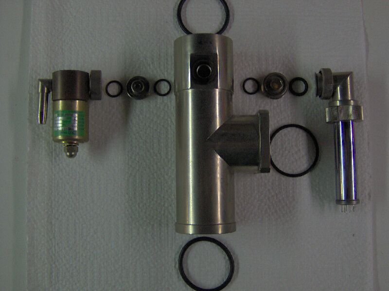
Moving on, here are the parts of the up-to-air solenoid valve (except
for the solenoid itself, which is wired to the microscope column and will
be installed later). Except for the o-ring seals, this valve seems
to be in pretty good shape, probably because it is a normally closed valve
that is only energized briefly during sample loading and hasn't had much
wear.
Up-to-air solenoid valve assembled.
Vacuum gauge and connector parts.
Vacuum gauge assembled to holder.
High vacuum manifold, with o-rings and connectors for up-to-air valve
and vacuum gauge.
High vacuum manifold with o-rings, up-to-air valve and vacuum gauge
installed.
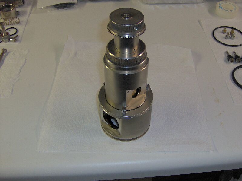
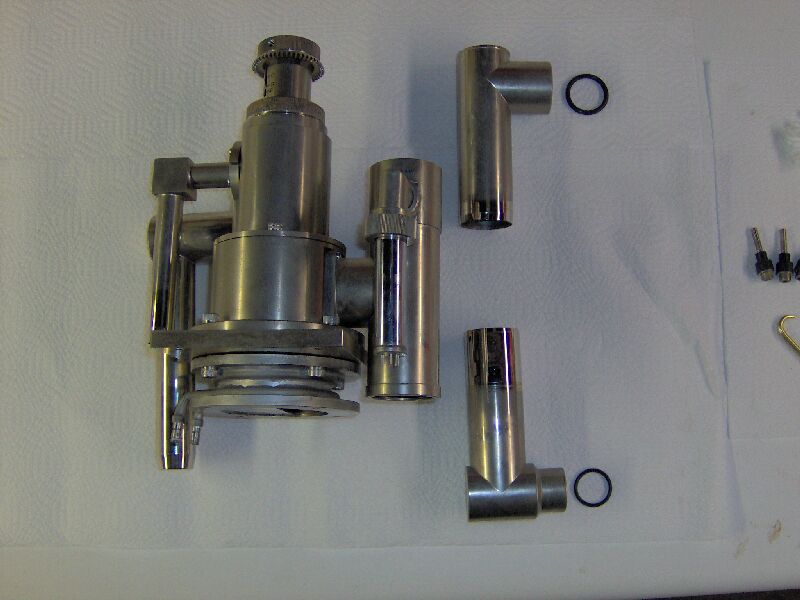
High vacuum valve ready to be connected to vacuum system support plate
(with water-cooled baffle attached), high vacuum manifold assembly, rough
vacuum line and rough vacuum to diffusion pump outlet line. Also,
I have connected a filter to the inlet of the up-to-air valve.
Assembled vacuum system (except for diffusion pump and anti-suck-back
valve). The upper and lower column connectors will be finessed into
place after this assembly is mounted in the column frame.
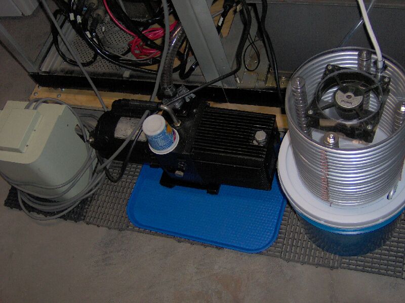
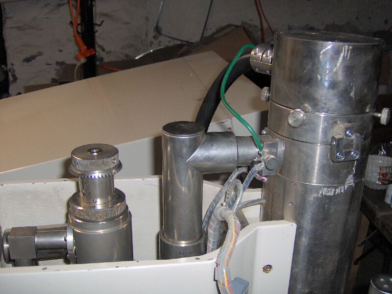
Here is the vacuum system mounted on the column frame and connected
to the column. The mounting plate was shimmed with five nylon washers
at each mounting point, in order to get the system at the right height
(partially for the alignment of the high vacuum manifold to column connector
pieces, but fine tuned to allow meshing of the gears between the valve
and the automated valve drive system, more on that later).
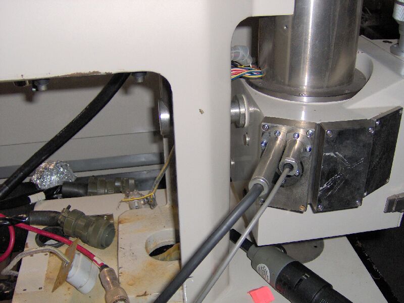
Here is another view, showing the top connection to the column.
And here is the bottom connection to the column (mostly hidden by the
column frame).
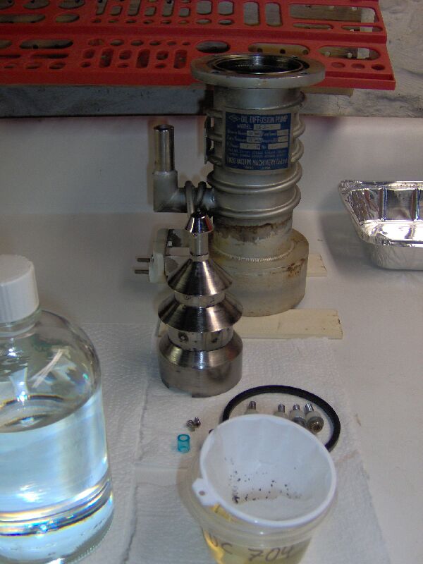
This picture shows the diffusion pump in the middle of an oil change.
According to the plaque on the pump, it requires 40 cc of oil. Draining
recovered 60cc of oil (Dow-Corning 704 silicone fluid), which was full
of black flakes. The oil was filtered leaving a clear, slightly yellow,
fluid of which 40 cc was returned to the pump. I have an almost full,
500 cc, bottle of fresh 704 fluid (left foreground) and thought about replacing
the pump oil altogether, but I'm cheap and this stuff is ~ $120 a bottle...
Also in the picture, you can see a small piece of blue, polyurethane, tubing,
from which I made a set of bushings to align the mounting screws in the
flange and the mounting screws, each with a set of six nylon washers to
properly shim the pump relative to the water-cooled baffle.
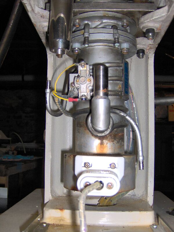
Diffusion pump oiled, jets installed, flange gasket lubed, bushed,
shimmed and bolted into the vacuum system, over-temp limit switch installed
and heater power cord connected.
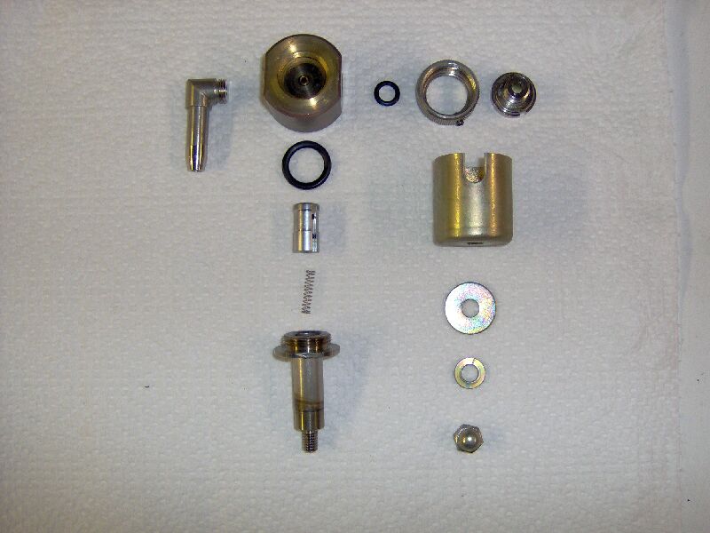
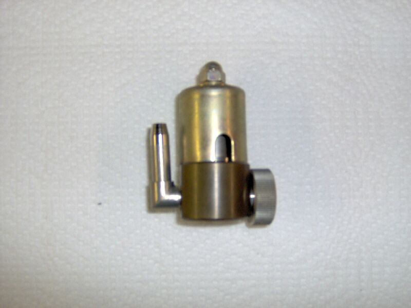
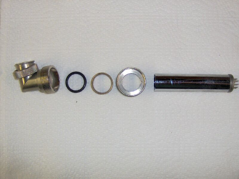
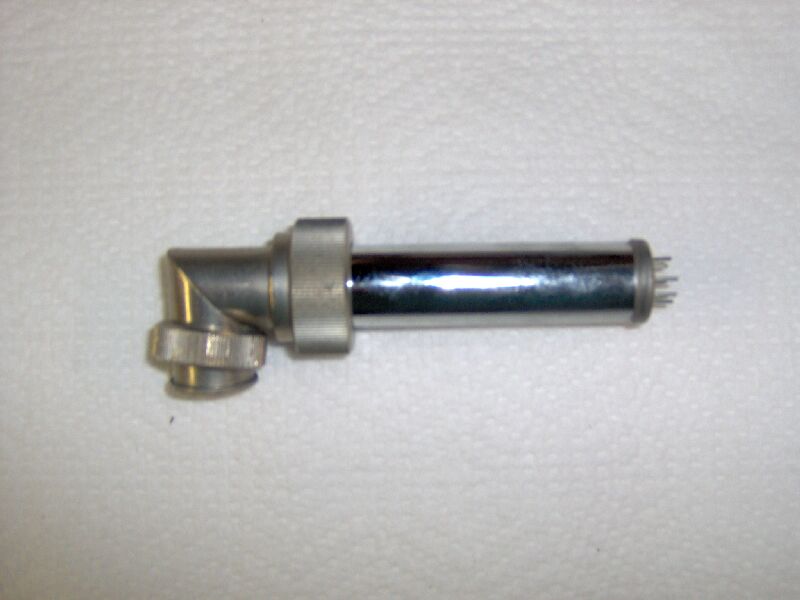
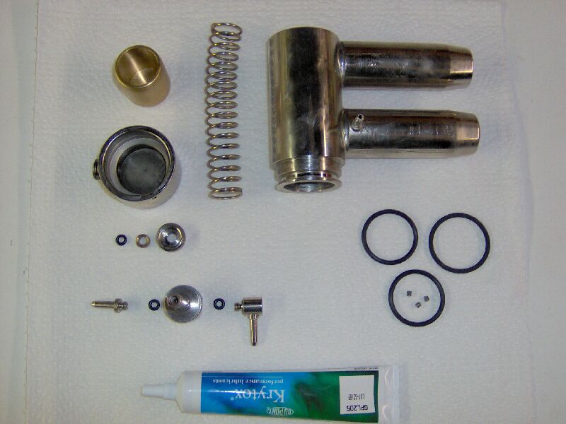
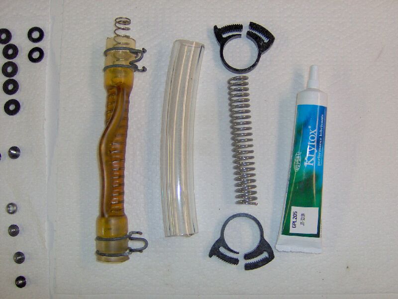
Next is the anti-suck-back valve. Here are the parts. I
opened the pilot solenoid valve (lower left, just above the grease) and
found that it was in pretty bad shape. This is a three-way valve,
with a poppet that has two seals. Both seals had compression-set
dimples from contact with the orifices. The bonnet seal was a flat
gasket molded to the bonnet and couldn't be replaced. The air side
of this valve was normally open, so in use, this valve was continuously
energized (and probably quite hot) accelerating wear.
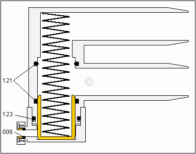
Anti-suck-back valve drawing, the numbers indicate o-ring sizes (aerospace
standard AS568A).
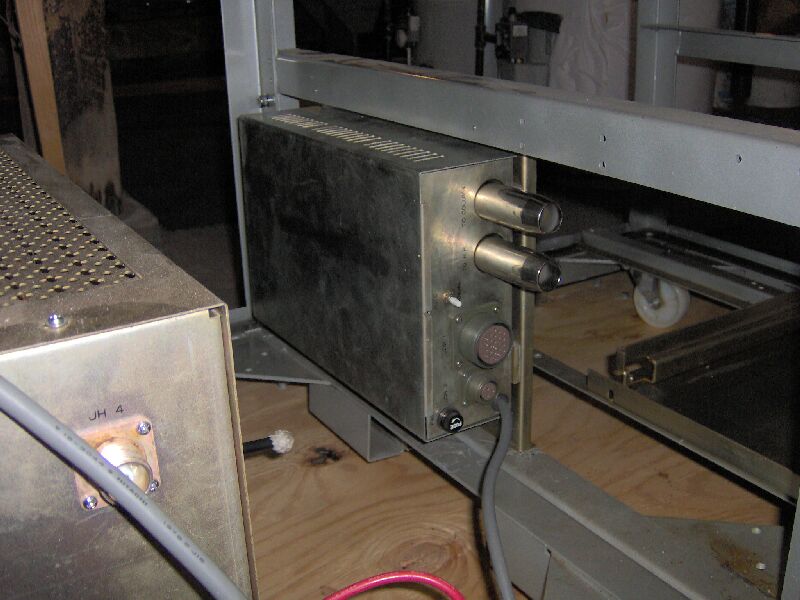
Installed in the vacuum logic chassis.
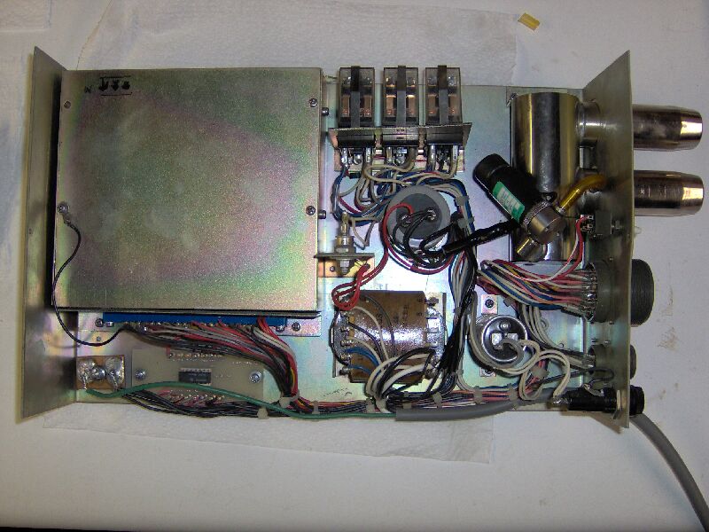
The vacuum logic chassis mounted on the instrument frame.
Let's hook it all together. First, the roughing line to the diffusion
pump. Because the clearances are all so tight in this system, the
manufacturer decided to use thin wall tubing, with internal support.
I've kept to that theme, but used heavier internal springs. The old
connecting piece is shown to the left of the new parts. You can see
that over time the old tubing collapsed down onto the spring, drastically
constricting the flow path. The new tubing is plasticized PVC, 5/8"
ID X 7/8" OD and the spring is 302 stainless steel, 5/8" OD.
The same method was used for the rough vacuum lines between the main
valve and anti-suck-back valve and between the anti-suck-back valve and
the rough pump. The tubing is plasticized PVC, 1" ID X 1.25" OD and
the spring is hard-drawn steel, 1" OD. Here is a pic of the line
between the valves.
Also, the line to the vacuum pump and the manifold connecting the pump,
tubing adapter and thermocouple vacuum gauge. The TC gauge should
come in handy during leak testing.
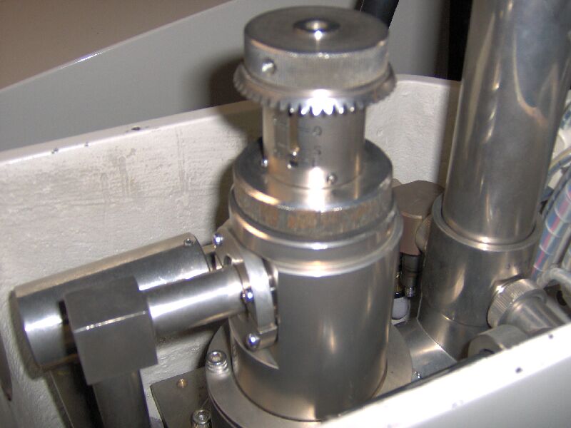
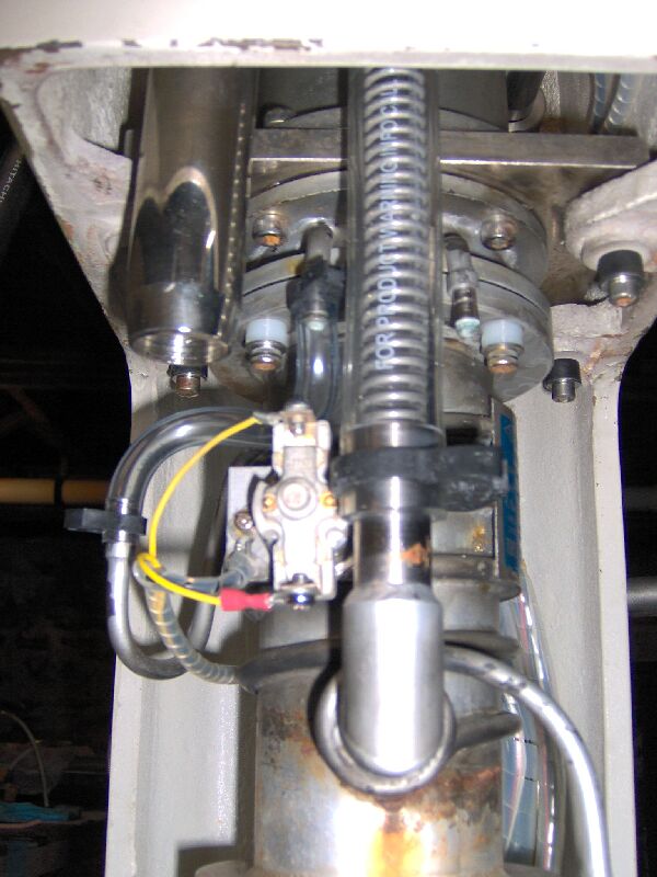
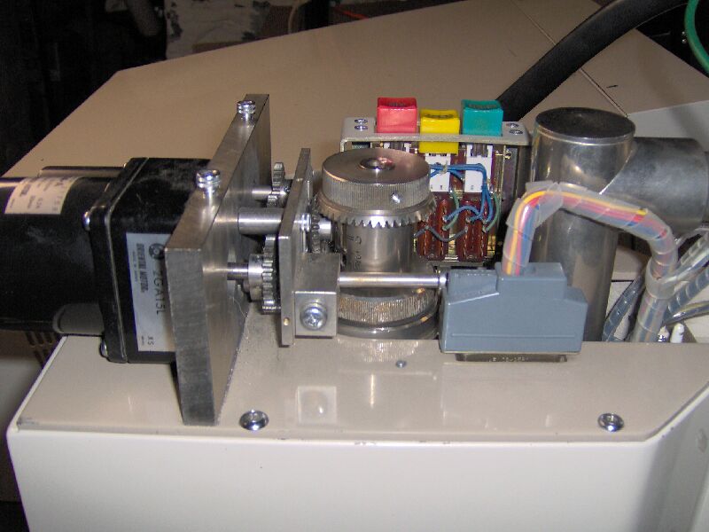
And here is the automated valve drive installed. In order to make
sure that the drive and valve lined up properly, I set the valve to the
shut position manually and then powered up the system with the drive also
set to the shut position (gratifyingly causing the motor to drive the gear
to the proper position) before screwing the drive into place.
Next, leak testing....
I powered up the SEM, and hit the "rotary pump" switch, which (although
my pump is not powered via the SEM, as was originally intended) was necessary
to supply power to the vacuum logic chassis and close the ASB valve pilot
solenoid. I then turned on the pump and found that the system wouldn't
even pump down well enough for the TC gauge to register on scale.
Time to back up a few steps. I disconnected the tubing from the pump
to the ASB valve at the valve and plugged it with a rubber stopper.
The TC gauge then came on scale and eventually bottomed out at a little
less than 200 microns (the pump is not improving with age). I reconnected
the pump to the valve, disconnected the tubing running from the valve to
the roughing connection of the 3-way, high vacuum, valve and plugged the
open ASB valve port with the stopper. In this configuration, the
TC gauge again failed to come on scale. This made me suspect the
pilot solenoid, which was now too hot to touch. After shutting everything
down, I removed the pilot solenoid valve and plugged the two connections
between it and the ASB valve (the o-ring fitting with a sawed off screw,
the shank of which was the right diameter to seal against the o-ring, and
the small tube with a greased rubber cap). In this configuration,
the pump could evacuate the ASB valve below 200 microns. The stopper
was removed and the ASB valve reconnected to the tubing from the roughing
line of the 3-way valve.
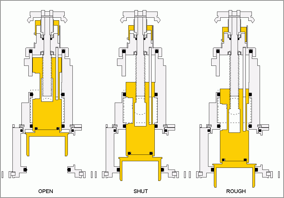
Time to try out the main valve. The SEM and mechanical pump were
turned on and the valve control "operate" button pressed. This caused
the valve to be driven from the shut position (see drawing below) to the
rough position. In this setting, the rough line (connected to the
back port, indicated by the dashed circle) is opened to the high vacuum
manifold (right port) and the microscope column. Both the diffusion
pump inlet (bottom port) and the diffusion pump rough line (left port)
are closed, isolating the diffusion pump.
With the 3-way valve in the rough position and the mechanical pump
running, the pressure indicated by the TC gauge slowly came down to ~ 400
microns, but wouldn't go lower. Also, the SEM vacuum gauge (a Pirani
style device) only barely came on scale. At first, I thought this
was due to a leak somewhere in the high vacuum system, but then it occurred
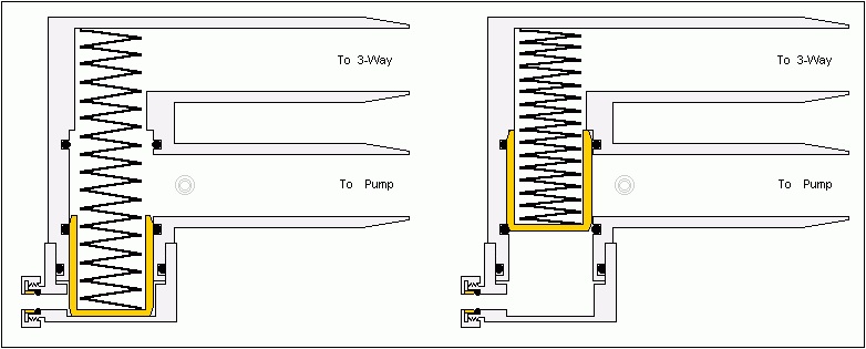
to me that the problem might lie with the ASB valve. Originally,
with the three-way solenoid valve acting as a pilot operator for the ASB
valve, in the energized state the o-ring (bottom left in the drawing below)
and tubular pilot (gray circles on the "to pump" port) ports are connected
to one another allowing the space behind the poppet to be evacuated by
the pump and the force of the spring to push the poppet into that space,
connecting the two main ports. In the de-energized state, the three-way
solenoid allows air into the space behind the poppet, pushing the poppet
closed against the spring force, while isolating the tubular port and leaving
both main ports under vacuum (pretty much guaranteeing that oil will suck
back from the pump to the ASB valve). With those two ports simply
plugged off and all ports at atmospheric pressure, the poppet is held in
the open position by the force of the spring (left side of drawing).
When the pump is turned on and the pressure falls in the main ports, the
air pressure trapped behind the poppet can force the poppet to partially
close and restrict the flow between the SEM and pump.
To test this theory, I replaced the plugs with a by-pass, made from
a short length of 5/32" OD X 0.015" wall 304 stainless steel tubing (to
fit the o-ring port) a length of 5/32" ID X 1/16" wall flexible PVC tubing,
a length of 8-32 threaded nylon rod (to act as a flow restriction) and
a couple of tubing clamps. The idea is that the flow restrictor will
allow the space behind the poppet to pump out during operation and the
poppet to open fully, while preventing an in-rush of air to the vacuum
pump during shut down, when I manually break the o-ring connection to allow
air in to close the poppet and vent the vacuum pump (more or less negating
the need for an anti-suck-back valve). At first, the TC gauge would
not register on scale, then I greased the join between the two pieces of
tubing, added another tubing clamp to that join and cranked the clamps
down with pliers (two notches past finger tight). If this works,
I'll order a tubing tee and manual valve to add to the bypass, so I don't
have to disassemble it for shut down.
With the by-pass leak tight and the pump running, the 3-way valve "operate"
button was pressed and the microscope column evacuated to an ultimate pressure
of a little over 200 microns on the TC gauge and the SEM vacuum gauge registered
a drop of ~ 1/6 of full scale (the meter is multi function and the vacuum
scale's only marking is a green "OK to operate" band which begins at 2/3
of full scale). Like TC gauges, Pirani gauges typically are wired
to give logarithmic outputs, suggesting that I have another 3 orders of
magnitude to go before the pressure is low enough for SEM operation.
Also, the pressure needs to be lower before the 3-way valve will automatically
cycle to the open position, engaging the diffusion pump. OK lets
shut down for the night, leaving the column under vacuum.
Hmmm... the column is no longer under vacuum. The microscope column
has two seals that are routinely made and broken, an o-ring at the top
for the electron gun and a molded gasket at the bottom for the sample chamber
door. I replaced the e-gun o-ring and removed, cleaned, greased and
re-installed the chamber door gasket. The column probably contains
more seals, but they are static and it's not obvious how to get at them.
Also, the chamber door contains a number of motion feed-throughs for moving
the stage (linear travel along three axis and rotation about two axis)
and I worry about the integrity of their seals, but, again, it's less than
obvious how to access them and I'm sure I don't want to pull apart the
stage mechanism (it makes your average mechanical watch look simple by
comparison).
Fingers firmly crossed, SEM powered up, vacuum pump on, valve "operate"
button pressed. TC gauge pressure is coming down, 1000, 500, 300,
200, 160 microns! Pirani gauge pressure has dropped past the 1/6
mark, approaching 1/3... and the valve drive is running! The 3-way
valve has cycled over to the "open" position, connecting the diffusion
pump to the system. Circulating
cooler turned on and diffusion pump switch depressed. The diffusion
pump base is getting hot, the Pirani pressure is going...up (? it's just
the oil degassing, it's just the oil degassing...). The side of the
diffusion pump is getting hot, the water is staying cool, the pressure
is going down 1/3, 1/2, 2/3, the green "operate" light is on, 5/6,
full scale!
Now I just need to spend some quality time with the manual and find
a specimen.
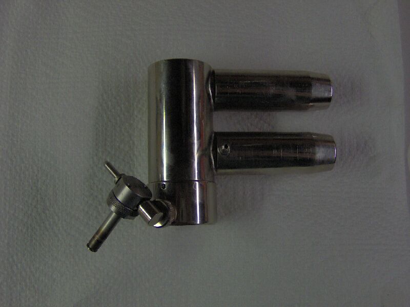
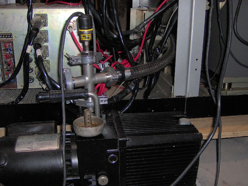
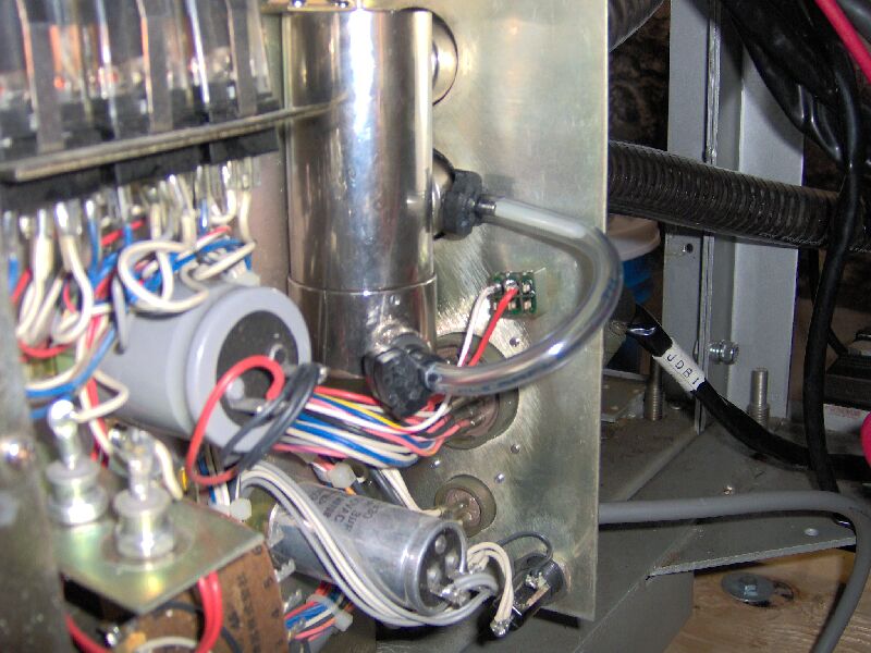
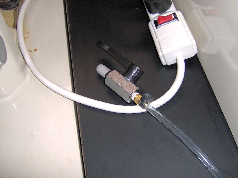
Sorry, a couple more things first. Ordered an 1/8" npt ball valve,
0.170" tubing tee, 1/8" npt air filter and 1/8" npt to 0.170" tubing adapter
to spruce up the bypass on the anti-suck-back valve. Here is a pic.
The ball valve and air filter are on the other end of the tubing which
exits the picture at lower left and sit on the console for easy access.
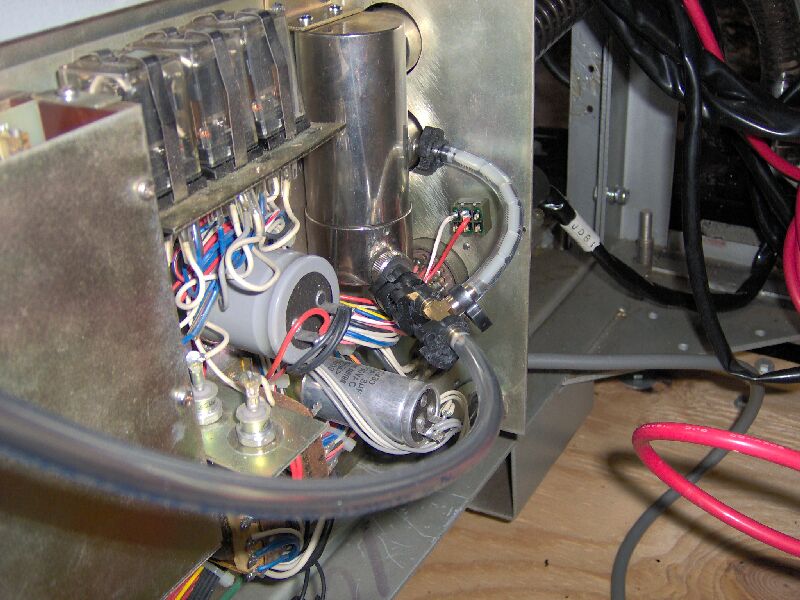
The other thing is that I have removed the thermocouple gauge and flanged
cross from the mechanical vacuum pump, removing four extraneous connections
from the system. Here is a view of the back of the instrument, with
the new vacuum connection. Also seen are the circulating cooler and
the giant wall-wart (for reasons known only to them, the manufacturer designed
the instrument to operate with a 100 volt input thus necessitating the
extra large adapter).