| Control | Function | Setting |
| Power Strip | Power to circulating cooler, vacuum pump and SEM | Off |
| Vacuum Pump | Power to vacuum pump | Off |
| Power | Power to SEM | Off |
| R(otary) P(ump) | Power to vacuum logic circuit | Off |
| D(iffusion) P(ump) | Power to diffusion pump | Off |
| Operation | Power to remaining electronic circuits | Off |
| Emission | Power to electron-gun filament | Off (fully counterclockwise) |
| Meter Selector | Chose vac(uum), emis(sion) or W(orking) D(istance) F(actor) | Vac(uum) |
| Dynamic Focusing | Compensates for sample T(ilt) (only use below 5000X) | 0º |
| High Voltage | Selects accelerating voltage | Low (2.5 KV) |
| Stigmator (X & Y) | Controls e-beam spot aspect ratio | 5.0 |
| Focus (Fine & Coarse) | Changes objective lens current (focuses e-beam on sample) | Center of 10 turns |
| Working Distance | Changes objective lens current to achieve focus in working distance range | 38 |
| Alignment (X & Y) | Electromagetically aligns e-beam to e-optics axis | Center of ten turns |
| Spot Size | Changes current in first condenser lens (clockwise decreases brightness of e-beam) | 2:00 |
| Signal Mode Selector | Couples various signals to the CRT including:
S(econdary) E(lectrons) B(ack) S(cattered) E(lectrons) X-ray L(ine) P(rofile) (X-Ray ratemeter to vertical axis) Spot (disables scan on CRT and in column, use with position controls) Line (disables vertical scan on CRT and in column, use with position controls) W(ave) F(orm) M(onitor) (disables vertical sweep, couples horizontal to CRT) |
SE |
| Position (X & Y) | Varies with signal mode | 12:00 |
| Scan Mode Selector | Changes vertical and horizontal sweep speeds | Rapid |
| Reduced Area | Provides reduced area scan (in rapid scan mode) | Off |
| Image Shift (X & Y) | Electronically moves raster on sample | 12:00 |
| Micron Marker | Displays micron marker on CRT | Off |
| Start | Starts single sweep (in photo scan mode) | |
| Contrast | Changes contrast of image | 12:00 |
| Brightness | Changes brightness of image | 12:00 |
| Magnification | Changes magnification in 24 steps | 30X |
| Zoom | Continuously varies magnification (1 to 3 X) | 1X |
| Electron Gun Alignment | Centers electron beam in column | |
| Valve Actuator | Automatically cycles high vacuum valve | Shut |
| Stage X | Moves sample under e-beam | 15.0 mm |
| Stage Y | Moves sample under e-beam | 20.0 mm |
| Stage Z (working distance) | Raises and lowers sample | 38 mm |
| Stage T(ilt) | Tilts sample under e-beam | 0º |
| Stage R(otate) | Rotates sample stage | |
| Stage Lock | Locks sample stage (to reduce vibrations at high magnification) | Unlocked |
Power strip on - fan and pump in circulator running, water flowing to diffusion pump. Anti-suck-back valve air inlet closed, mechanical vacuum pump on. SEM power on, rotary pump switch depressed, column air button pushed - column pressure comes up to atmospheric. Open sample chamber, place dime (washed with isopropanol) face down on center of sample stage, tape to stage with conductive adhesive backed copper foil tape. Close sample chamber, press column operate button - high vacuum valve cycles to "rough" position - column pressure begins to drop. Column pressure drops to ~ 1/3 of scale - high vacuum valve cycles to "open". Diffusion pump switch depressed - diff pump begins to heat. Diffusion pump hot - column pressure falling. Column pressure falls to ~ 2/3 of scale - green "OK to operate" light comes on. Wait 15 minutes - vacuum gauge firmly pegged at bottom of scale.
Double check control settings, switch meter selector to emission and operation switch depressed - operation switch and photometer lights come on, emission meter reading increases to ~ 5 microamps, a rapid scan line (top to bottom) shows on the CRT, but nothing like an image is visible. The manual claims that I should be seeing a "scanning area about 5cm high x 6cm wide" (I've since figured out that the problem was that I was in "reduced area mode" but I didn't get that until much later.) I fiddled with the contrast and brightness controls for a while, but these only produced varying levels of snow. I decided to go ahead and perform the "saturating the filament" step, by cranking up the emission control until the emission current reading maxes out (without exceeding the 2:00 setting on the emission control, as per several dire warnings in the manual). Doing this produced an emission current of ~ 95 microamps (which, according to the manual, indicates that I have an old, tired filament [new filament current should be ~ 175 microamps, nearly dead filament ~ 90 microamps]). More contrast and brightness fiddling produced no recognizable image. At this point I killed the emission current, shut off the "operation" switch and sat down with the manual for a while.
In my previous reading I vaguely recalled a section of the manual which listed the stage center positions for the stage controls. After checking that section again, I realized that the stage position settings were such that the sample might not be in the field of view. The stage should be centered relative to the electron beam at settings of X = 32 mm and Y = 20 mm. Since the 18 mm in diameter dime was centered on the 76.2 mm OD stage and the stage center was off by 17 mm it was clear that I was centered on the featureless stage. Armed with this knowledge, I turned the operation switch back on, saturated the filament as before and cranked the stage X control to 32.0 mm, keeping a close eye on the screen to see if anything became visible. Nothing did.
At this point I began thinking dark thoughts about dead photomultipliers and fried integrated circuits. I turned the emission control down and flipped off the operation switch. I opened up the photomultiplier housing and found a pristine appearing Hamamatsu R268 tube. A quick google search lead to a site listing specs for a variety of photomultiplier tubes, including the R268. A footnote also mentioned that the tube had been discontinued, but could be substituted with Hamamatsu's R6095 tube (same size, pin-outs, and specs but flimsier internal construction). More searching convinced me that I wasn't going to get my hands on a new tube in a timely fashion (if at all), so I went back to the manuals (I actually have two copies of both the main manual and the "operation guide"). I had been reading from the less ragged main manual but decided to check the other manuals. In the beat up main manual copy I found a hand written note in the margin next to the text describing the method I had used to saturate the filament which said "don't use this technique". The only other technique mentioned (in the operation guide) involved using the wave form monitor signal mode, in which the vertical sweep of the e-beam and CRT is disabled and the photomultiplier output is coupled to the horizontal axis of the CRT. In this mode the e-beam scans a single line across the sample and the CRT shows a line with peaks and valleys corresponding to "bright" or "dark" (i.e., ejecting more or fewer secondary electrons) areas of the sample along the scan line. In this procedure, saturation is achieved by adjusting the emission control to maximize the peak heights. Back to the 'scope: operation switch depressed, WFM mode selected, brightness and contrast adjusted to obtain a noisy line across the CRT. Emission control rotated clockwise - the line gets noisier and rises (I think this means the photomultiplier is OK!) but no peaks form. Adjustment of the coarse focus control across its full range of travel likewise failed to elicit any peaks. Back to SE mode, emission off, operation off, DP off, column shut, mechanical pump off, let diffusion pump cool about an hour, power strip off, go to bed.
Another session with the manual and I'm pretty sure that the filament is OK (emission wouldn't change otherwise) and the photomultiplier is OK (wouldn't be any signal in WFM mode otherwise), and that my sample is centered. About all that leaves is electron beam intensity, which (besides emission) is effected by electron gun alignment and spot size controls. Another review of the operation guide suggests that spot size should be higher than I have been using and should be set at the 10:00 position to start. Fire up 'scope as before, saturate emission (using the emission meter, not WFM) and crank the electron gun alignment knobs while watching the photometer reading (which, near as I can figure, provides an integral of CRT brightness over the sweep area). With the photometer adjusted to half scale (using brightness and contrast controls), I was able to peg the photometer by adjusting the e-gun alignment knobs. I then brought the photometer reading back to 50% by adjusting the brightness and contrast controls, and back to 80% with the alignment knobs. Unfortunately, I ran out of mechanical play on the adjustment knobs, while the photometer was still rising, so I'm pretty sure that alignment of the electron gun is still off, but way better than it was. With signal mode set for secondary electrons, scan mode in rapid, spot size at 10:00, I began moving the sample position X and Y controls in an attempt to find the dime. After a while I became convinced that I could see a very faint arc (the edge of the dime?) which was moving on the CRT in response to my inputs. By adjusting the stage R control, this faint image changed to include a straight line intersecting the arc (the edge of the copper foil tape?).
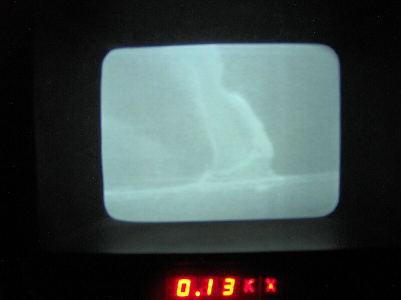
At this point I decided to try cranking up the accelerating voltage. I turned the emission control down to minimum, and clicked the high voltage control over to medium (15 KV) and noted that the emission reading rose to ~ 30 microamps. I turned up the emission control to saturate the emission current as before, getting a maximum of ~ 100 micramps. The image seemed to be a bit more real, so I decided to go full bore on accelerating voltage. Emission down, high voltage to high (30 KV), enission up to ~60 microamps, turn up emission control, saturation current ~ 105 microamps, image a little bit better. I tried to get a picture of this, but it was too faint for my digital camera, so I captured a short video instead. Even more convinced that I had something, I tried various scan modes and found that the "TV" scan mode gave a much clearer image (I also found that I had been running in reduced mode when using the rapid scan setting, but turning off reduced mode didn't improve the image at all, only made it smaller [counterintuitive, that]). Not sure why I tried it, but I found that increasing the magnification actually gave a sharper image. Adjusting the coarse focus control made no difference, but turning the spot size control down (clockwise to 11:00) improved the image again, as did a further increase in magnification (300X on the control, ~ 130X actual, taking the working distance into account). Here is a picture of the CRT image (taken with flash off to force a long exposure time, camera on a tripod and in timer mode so that it would be rock steady during the long exposure) showing the edge of the dime and one of the pieces of copper foil tape. At this magnification, the knurled edge of the dime looks like some sort of giant gear tooth. At the bottom of the image is the LED readout of the actual magnification factor of "0.13KX", or 130X.
Been thinking about the e-beam alignment and running out of mechanical play while trying to adjust it and decided to try moving the e-gun against the o-ring seal. I found that there was some play in the direction needed to overcome the lack of play with the alignment knobs, so I slid the entire e-gun assembly (less than a mm) in that direction. I then went through the start up and alignment procedures as before and was able to achieve a true maximum on the photometer. I tried refining this with the X&Y alignment controls (which steer the e-beam electromagnetically), but didn't improve the photometer reading. The resulting image was a little clearer than it had been, so I decided to try higher magnification. Above ~ 5000X, moving the sample with the stage X, Y and R controls became somewhat difficult, so I tried out the X and Y image shift controls, which worked as advertised, moving the scan area over the sample. Also, the coarse focus control began to make a difference and I was able to keep the image in focus (although still rather faint and with low contrast) up to ~ 40,000X. Just as I started thinking about taking a picture, the CRT went blank and a faint buzz came from the e-gun. I knew the filament was old, so I wasn't completely surprised when it burned out. I turned down the emission control, turned off the operation switch and went through the rest of the shutdown procedure as before.
After going through the user's log, I found that new filaments typically last ~ 20 runs. I have some new filaments, but I figured I'd better check to see if I could get more and also see what other supplies were available. The user's log also noted fairly regular cleaning of several of the column's internal parts. A check of the manual showed that the recommended cleaning procedure required "Wenol" metal polosh. A google search on SEM supplies led me to several vendors. After skipping the ones out of country (two in Canada, one each in Australia and the UK) and doing some price comparisons, I found that M.E. Taylor Engineering had by far the best prices on filaments ($275.00/pkg 10), but didn't carry Wenol (although a number of the other vendors did). A separate search on Wenol turned up a number of restaraunt supply stores and motorcycle and car parts places that carried it. I called around locally to a bunch of restaraunt and automotive supply stores, but nobody I talked to would even admit to having heard of Wenol, let alone carrying it. I eventually ordered two tubes of Wenol from Webstaurant . While checking out the various SEM supply vendors, I noticed that they all carried several varieties of scintillators, usually listed under "consumables", along with the filaments. I vaguely recalled Jace having said something about the scintillator being old and I began to wonder if the scintillator was part of the reason the image was so dim and vague. Scintillators are an integral part of the image formation system. When struck by secondary electrons from the sample the scintillator emits photons, which are converted into an electrical signal by the photomultiplier tube. There is no mention of the scinillator ever having been changed in the user's log, which goes back to July of 1992. The manual does list a procedure for changing the scintillator, which requires silver paint for making electrical contact between the phosphor coating of the scintillator and the scintillator mount. M.E. Taylor also seemed to have good prices on scintillators and silver paint, so I ordered an ISI (13.5 mm OD) P47 scintillator ($89.00) and a jar of silver paint ($18.00). I'll wait until the Wenol, scintillator and paint show up before I try changing the filament, that way I can go ahead and clean the column's internals while I'm at it.
While I was waiting for the new scintillator, silver paint and Wenol, I found four sets of clean electron gun cartridges in one of the boxes of parts that came with the 'scope and decided to try changing the filament. With a new filament in place, I turned on the instrument as before, saturated the filament (180 microamps, right about where it should be for a new filament) and found little or no improvement in the observed image.
Paint, scintillator and Wenol have arrived. I changed
the scintillator, fired up the 'scope and was dissapointed to find
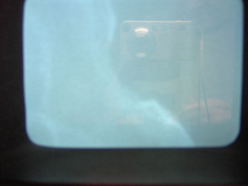
only a very slight improvement in image quality. Here is a picture
(no flash, timer) of the image of the dime at 420X (the visible feature
is one of the indentations between knurls on the dime's edge, you can also
see a reflection of the camera [I'll have to remember to turn that light
off next time]).